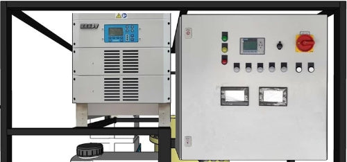
Spiral-Electrocoagulation (S-EC)
Celsa is the authorized distributor of Spiraltec’s patented Spiral-Electrocoagulation (S-EC) test equipment in Australia, offering cutting-edge solutions for industrial wastewater treatment. S-EC technology optimizes flow hydrodynamics, improving energy efficiency while enhancing contaminant removal. With automatic operation and an integrated monitoring system, it ensures seamless and efficient wastewater management.
Contact us to learn how Spiraltec’s innovative S-EC technology can support your treatment needs.

Production Capacities for Industrial Wastewater Treatment
The S-EC series provides efficient electrocoagulation treatment with capacities ranging from 10 m³/d to 50 m³/d, ensuring reliable performance for diverse industrial applications.
S-EC 10 – 10 m³/d treatment capacity
S-EC 20 – 20 m³/d treatment capacity
S-EC 30 – 30 m³/d treatment capacity
S-EC 40 – 40 m³/d treatment capacity
S-EC 50 – 50 m³/d treatment capacity
Process optimization through innovative electrode configuration

Three processes integrated into a single system
1. Spiral-electrocoagulation (S-EC) with stirrer
2. Electroflotation
3. Sludge settling tank
Flow hydrodynamic optimization
An efficient EC configuration would preferably provide a uniform flow distribution between the electrodes. To compare the flow hydrodynamic of the spiral electrocoagulation (S-EC) with the conventional EC (vertical plates), a fluid flow simulation using Computational Fluid Dynamics (CFD) with similar dimensions and conditions was performed (see Fig 2).
As it can be seen, the uniformity and increased velocity in the spiral EC have been enhanced than the conventional EC. In the conventional EC, the vertical plate electrodes serve as a barrier against flow circulation, so then flow cannot be circulated and distributed evenly between the electrodes. This is a condition under which, fouling is anticipated to occur under the passivation of electrodes. Under such circumstances, fouling potential increases on the anode electrode and reduces the mass transfer coefficient.

Energy consumption optimization
Fig. 3, compares the voltage rise between the conventional EC and spiral EC configurations. To reduce energy consumption, the voltage should be reduced as much as possible. In general, two reasons can be expressed for increasing voltage in ECF. First, the development of a passive film on the anode, and second, the generation of hydrogen gas on the cathode.
These issues increase electrical resistance and hinder optimal removal results, requiring excessive energy consumption. To address these problems and prevent voltage rise, enhancing flow hydrodynamics around the electrodes is crucial, pushing out bubbles and improving mass transfer near the anode. The spiral EC configuration, depicted in Figure 3, shows promising results with lower voltage experienced across all concentrations, suggesting a potential solution to mitigate these challenges.

Case Studies

Feed from Metal Industry

Milky Wastewater from Dairy Cattle Septic Systems and CIP Processes

Feed from Textile Industry

Proof of Concept & Demonstration
Electrocoagulation Knowledge Base
More about Spiral-Electrocoagulation (S-EC)
Spiral-Electrocoagulation (S-EC) by Spiraltec GmbH offers cutting-edge technology designed with your needs in mind. This technology is engineered to treat a diverse range of contaminants across a multitude of industries.
What makes our S-EC system special is its unique spiral electrode configuration, which optimizes flow hydrodynamics, thereby saving energy and improving contaminants removal efficiency.
Moreover, the system operates automatically and features a built-in monitoring system, enabling you to easily track key parameters such as pH, conductivity, temperature, etc. both before and after treatment.
How does Electrocoagulation (EC) work
In EC, when an external direct current voltage is applied, then different electrochemical reactions may take place at the anode and cathode of an electrolytic cell. EC involves the generation of in-situ metal coagulant by electrolytic dissolving sacrificial anode materials (aluminium or iron).
In case of aluminium, the anodic process, involves the oxidative dissolution of aluminium into aqueous solution which is presented in reaction (1). In the cathode, the reductive dissociation of water would also take place, see reaction (2).
|
Anode
|
Al(s)→Al3+(aq) + 3e−
|
(1)
|
|
Cathode
|
2H2O + 2e− → H2(g) + 2OH−(aq)
|
(2)
|

Aluminium ions (Al3+) produced by electrolytic dissolution of the anode, which act as coagulant reagent, hydrolyze and form mono-nuclear complexes according to the following sequence:
|
Al3+ +H2O → Al(OH)2+ +H+
|
(3)
|
|
AlOH2+ + H2O → Al(OH)+2 + H+
|
(4)
|
|
Al(OH)+2 + H2O → Al(OH)3 + H+
|
(5)
|
|
Al(OH)3 + H2O → Al(OH)-4 + H+
|
(6)
|
Applications of Electrocoagulation Technology
Electrocoagulation is a versatile method for wastewater treatment that finds applications across various industries, encompassing, but not limited to:
- Oil refinery, gas exploration, and production
- Petrochemical industry
- Textile industry (e.g dyeing)
- Food and beverage processing
- Pulp and paper manufacturing
- Mining and metal processing
- Chemical and pharmaceutical production
- Slaughterhouse
- Landfill leachate treatment
- Electronics and semiconductor manufacturing
Contaminants Removal
Electrocoagulation can effectively treat a wide range of contaminants found in various wastewater streams. Some common types of contaminants that can be treated through electrocoagulation include:
Contaminant |
Compounds |
|
Suspended Solids
|
particles, colloids, and sediments
|
|
Heavy Metals
|
lead, chromium, cadmium, arsenic, and mercury
|
|
Organic Compounds
|
oils and Fats, Surfactants, Phenols, Dyes and Pigments
|
|
Organic Compounds
|
oils and Fats, Surfactants, Phenols, Dyes and Pigments
|
|
Bacteria and Pathogens
|
bacteria, viruses
|
|
Turbidity and Color
|
caused by suspended particles and dissolved substances
|
|
Inorganic Ions
|
sulfate (SO4), fluoride (F)
|
Publications
1. Impact of operating parameters of electrocoagulation-flotation on the removal of turbidity from synthetic wastewater using aluminium electrodes.
2. Innovative spiral electrode configuration for enhancement of electrocoagulation-flotation.
